RSEA SHIP
Marine air bag
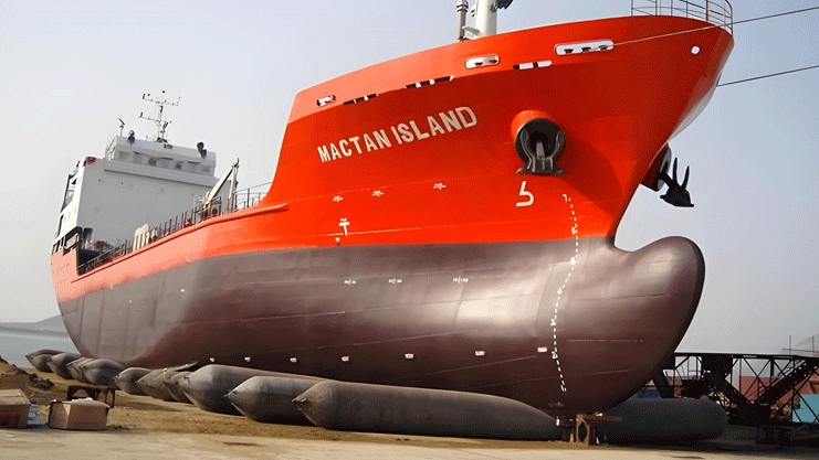
Rsea Ship Launching Airbags are designed and manufactured according to ISO 14409. Nowadays, our various performance indicators have far exceeded ISO14409 to provide improved durability and safety performance. ISO17682 methodology for ship launching utilizing airbags makes safety ship launching.
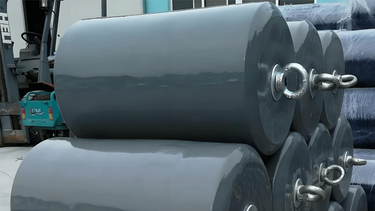
Rsea Ship Launching Airbag diameter size from 300 mm to 4,000 mm and length from 3,000 mm to 33,000 mm, and offer customized size manufacturing service.
Rsea ship launching airbag uses a cross-wound process, which can withstand greater impact. The service life is more than 8 years, and other Chinese factories mostly use synthetic rubber.
PRODUCT DETAILS


Application: Ship launching/upper discharge
Diameter: 0.5m-3m custom
Effective length: 1m-32m customized
Number of layers: 5-20 layers customized
MARINE AIRBAG STRUCTURE

ADVANCED MATERIALS FOR MARINE AIRBAGS
EXQUISITE PRODUCTION TECHNOLOGY
MARINE AIRBAG BENEFITE AND PERFORMANCE
The following parameters are the dimensions and parameters of standard Marine airbags.
However, Marine airbags have developed different product schemes according to different project requirements. The project party shall provide the corresponding ship type, size and weight. The technical department can issue the project product plan, or the project can directly provide the required Marine airbag model specifications.
MESSAGE
RELATED PRODUCTS
 EVA foam fenderEVA fender, polyurethane solid filled fender is a compression fender, which uses polyurea elastomer material as the outer protective layer and high-density closed cell rubber and plastic foam material as the buffer medium. In the process of use through its compression deformation to absorb the impact energy of the ship, so as to reduce the damage to the dock and the ship. Foam filled EVA fender is made of environmentally friendly materials and highly elastic polymer materials. The product has high strength, high elasticity, high adhesion, anti-leakage, anti-aging and other high performance, has a high service life and high economic value.
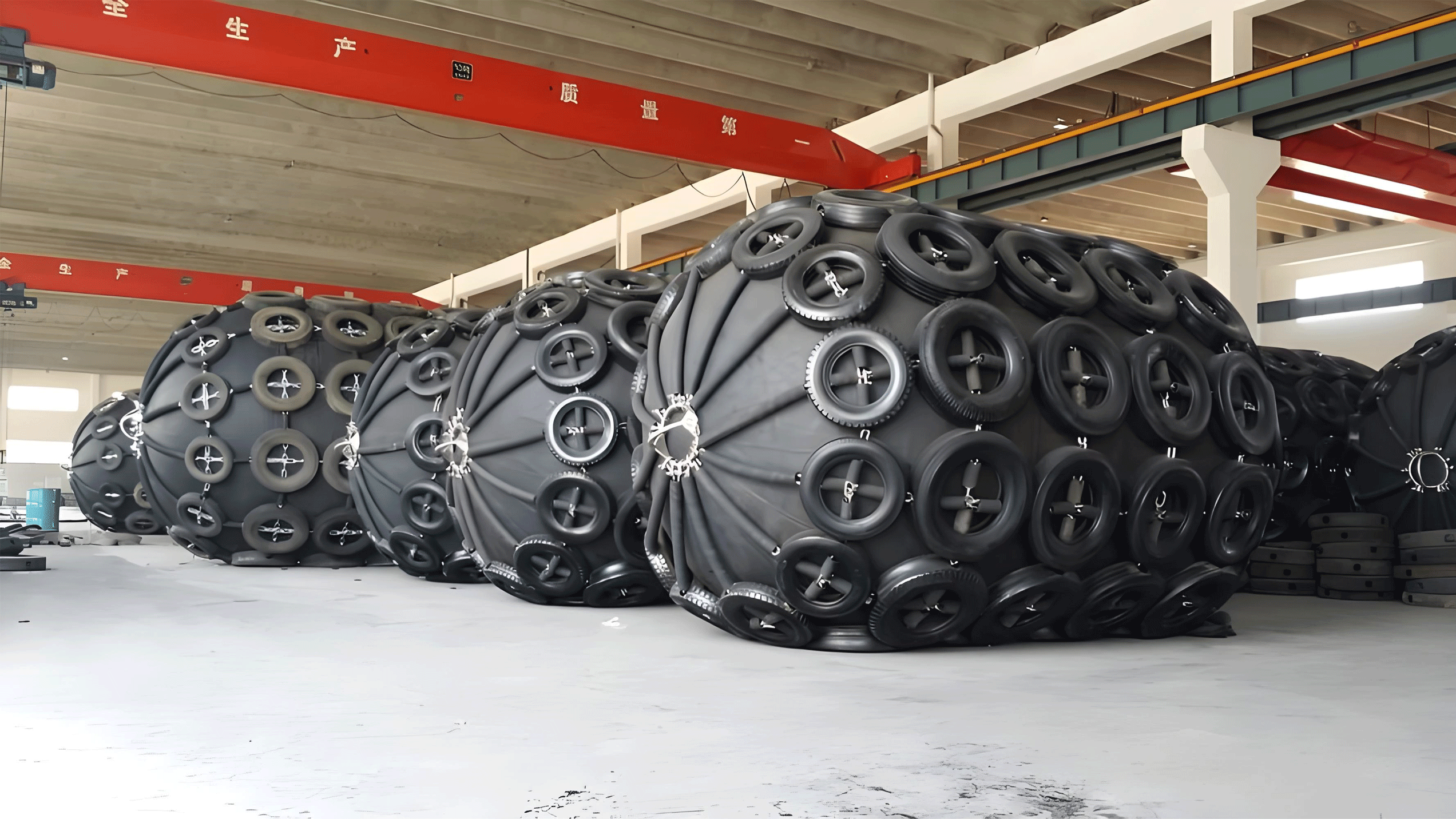
 Pneumatic FendersInflatable Marine fenders are commonly used for ship-to-ship transfer fenders and are also used for ship-to-moor operations in shipyards/docks. It was previously invented by the manufacturer of YOKOHAMA, so it is now also called Yokohama Marine fender or Marine anchorage ball.
Marine ball after years of improvement, the use of special production technology and high-performance materials, so that it has better energy absorption characteristics. Marine ball installation is convenient, foldable delivery, for buyers to save 2/3 of the transportation cost, is a better choice to protect large ships. Super Cone Rubber FenderCone-type solid rubber fender is the third generation fender with excellent performance and efficiency. The conical shape makes the conical rubber fender very stable even at large compression angles.
Conical solid rubber fender is an efficient rubber fender that can be used in a variety of applications. It has a conical shape and mounting flanges fully embedded in rubber. Its delicate geometry and tapered shape make for a number of outstanding performance characteristics.
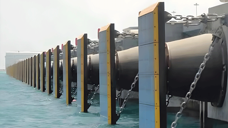
Cone solid fenders range in height from 300 to 2,000 mm for excellent performance and efficiency. The cone shape makes the conical fender very stable even at large compression angles and provides excellent shear strength. As the overload stops, the conical fender is more resistant to excessive compression. Super Arch Rubber FenderThe arch solid rubber fender is a simple and robust Marine fender system that provides reliable and trouble-free service for a variety of berths, even in harsh conditions.
The arch solid rubber fender is an upgraded version of the V-arch fender, optimized for increased energy absorption compared to the traditional arch fender.
The arch fender can be provided as a single element or as part of a complete fender system.
They are particularly suitable for ships with high allowable hull pressures and limited installation space.


